Even though smaller piston ring packages have been incorporated for some time now, their integrity is still challenged by some. That being said, this is not so much a concern among engine builders as it is for consumers or the end user. To help better understand where this conversation is going, when a smaller ring package is mentioned it automatically becomes a potential problem.
People automatically assume that for some reason a smaller ring package will cause oil consumption and sealing issues, when, in fact, the smaller piston ring packages not only free up some horsepower but also provide better cylinder sealing. To some customers this “new” technology has some mental blockages. When you tell the customer the piston ring package used in their engine they cringe. It’s like you built their engine with a flaw and the rings are going to fail.
Now that being said, there have been a ton of articles relating to piston rings. So I don’t want this to be the straw that breaks the camel’s back, I just want to point out some very interesting results we obtained from a recent piston ring test using pistons and rings from MAHLE Motorsports. I am sure that we all are familiar with traditional piston ring packages being 5/64-inch, 5/64-inch, and 3/16-inch. These piston ring widths are still used for general rebuilds today, but were the only piston ring widths available back in the day. As the years passed smaller widths were used — such as 1/16-inch top and second rings with a 3/16-inch oil ring — and are still common today.
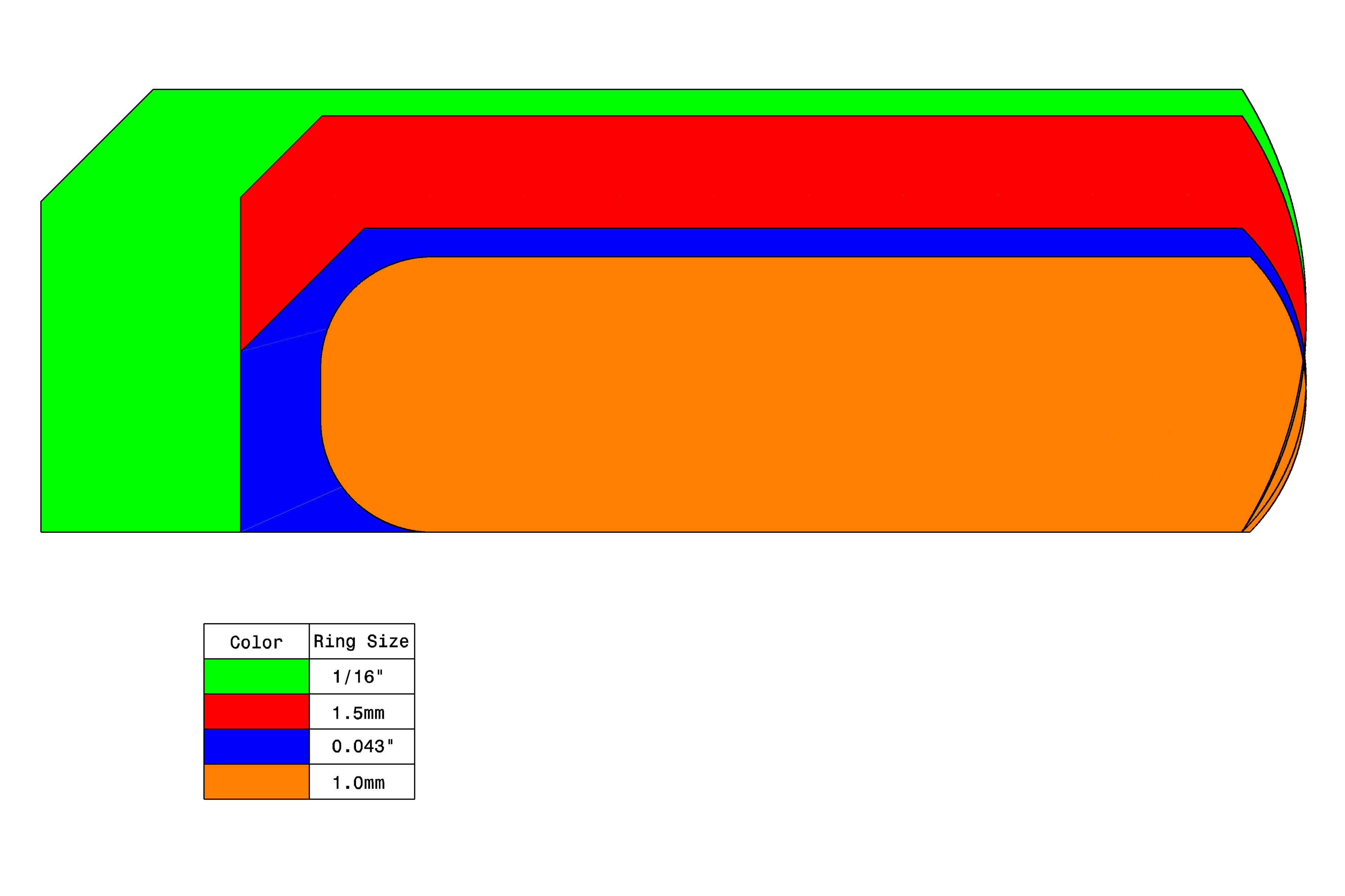
The graphic shows the relative size comparisons in both radial width as well as ring thickness between the ring sizes tested. While 1/16-inch rings might not sound that different from 1.0mm rings. If you convert them both to decimals (.062 vs .039), the almost 40-percent difference in size becomes far more apparent.
It’s not like this piston ring technology is new. NASCAR teams have used small piston ring and wrist pin packages for years with great success. In fact, technology was progressing so fast, that NASCAR ruled that the piston ring widths had to be at least .035-inch thick because the race teams were getting out of hand.
When the OE started introducing smaller ring packages into production engines people started to take notice. But, when smaller ring packages were being introduced as performance options or upgrades for their engine build, people began to become concerned.
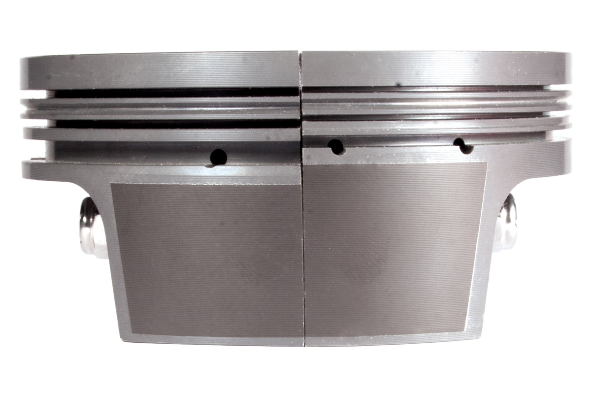
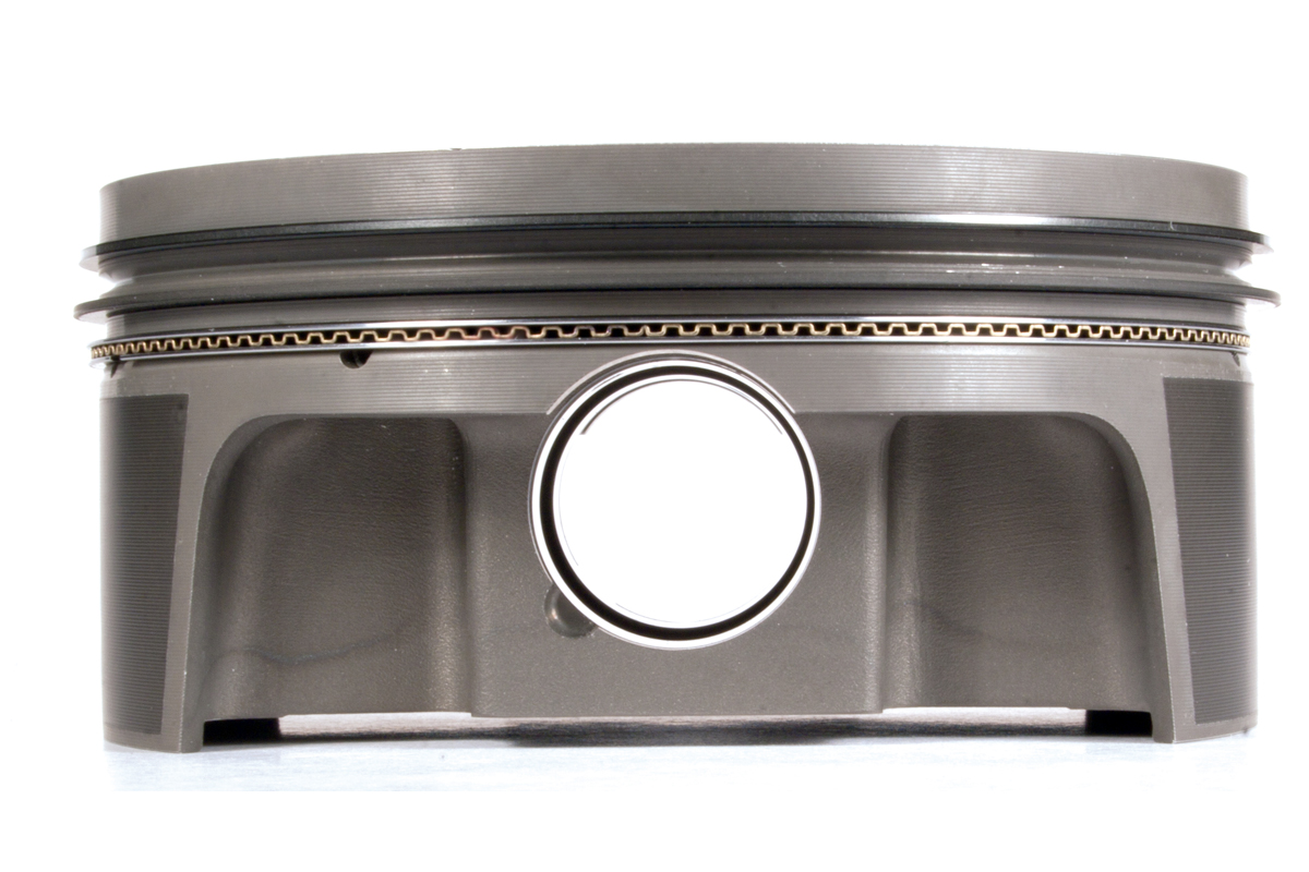
This is a side-by-side cutaway of two MAHLE pistons showing a 1.5mm, 1.5mm, 3.0mm ring pack on the left; compared to a 1.0mm, 1.0mm, 2.0mm ring pack on the right. One thing not visible at this angle is that the thinner ring pack doesn’t intersect the wrist pin bore.
Setting Up the Test
There is telling a story with words, and then there is telling a story with tests. Even though there have been some dyno tests in the past to show that there are some power gains in using smaller piston rings, We felt there needed to be a comprehensive test of several different piston ring widths to see what we started with to where we have evolved to.
Several tests would need to be conducted, starting with the thickest piston ring package first and then work our way down to the smallest. The important factors to analyze would be the bore finish before and after each piston ring test along with measuring the engines blow-by during each piston ring test.
The idea was to build an engine very similar to Ford Performance’s 347 crate engine without the use of any custom parts. The thought process of the engine build was not to outperform the crate engine but to replicate the results as closely as possible by using good internal engine parts along with some good machine work. Basically, an engine build that most engine building professionals would perform in their shop.
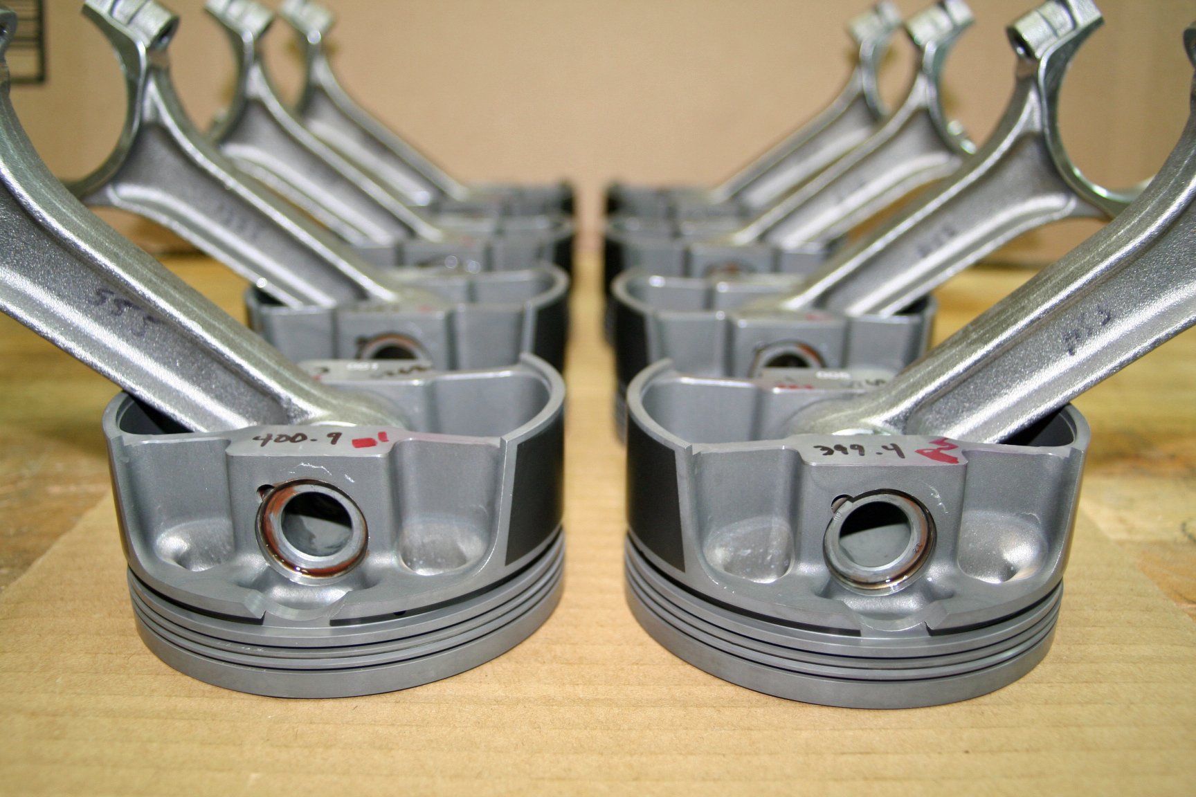
For the piston ring test MAHLE produced four different sets of pistons containing the four different ring widths. All of the pistons were .030-in. oversize and had a valve relief volume of 6.5 cc. They were also all weight matched to eliminate the need to rebalance between tests.
The biggest challenge of the build would be to configure everything to be able to “hot swap” four sets of pistons and rings on the dyno. The pistons and rings had to weigh-in very close to each other so the balance of the engine wouldn’t be affected. After MAHLE manufactured all of the pistons, the weights of the four different sets were within 4 to 6 grams of each other.
The plan was to start with the thickest piston ring package first which would be the 1/16-, 1/16-, and 3/16-inch widths. Once the engine had completed the break-in period, the engine would be tested and fine-tuned for maximum torque and horsepower. After the power readings were established we would then take readings from the blow-by meter to establish the amount of piston ring leakage taking place (measured in CFM).
The first test would provide the baseline so as data from each subsequent test using smaller width piston rings came in, we had something to compare it to. Upon each tear down, the cylinder bore finish was analyzed and measured with a profilometer to see the progressive wear effects the piston rings were having on the cylinder bore finish.
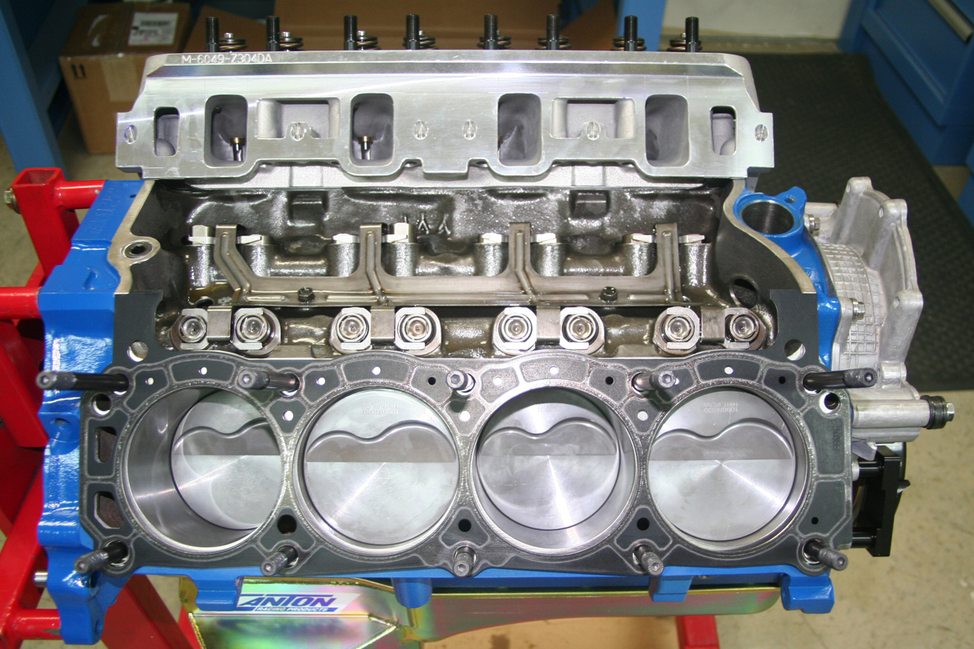
An affordable solution to simplify the engine build was to purchase a machined block from D.S.S. racing. The Level 20 CNC stock block was bored, stroker clearance, threaded freeze plugs, and decked to our specifications. The forged crankshaft and connecting rods were purchased from Scat. The crankshaft has been internally balanced using 302 main journals with 3.400-inch stroke using 5.400-inch connecting rods with 302 rod journals
Styling and Profiling
To measure the wear in the bore, we used a tool called a “profilometer.” The profilometer is an electronic instrument with a diamond tipped “finger” that is dragged across the surface finish to read the honing finish of the bore. In simple terms, it’s a way to get a microscopic view of the freshly honed cylinder.
Different rings require different honing procedures and a true way to know the desired finish of the cylinder is to use a profilometer. When the bore is looked at through a microscope you can see that there are small peaks and valleys formed by the abrasives used in the honing process. To obtain the proper cylinder wall finish for their particular rings, the piston ring manufacturer often specifies the “grit” of the abrasive to use to achieve this finish.
The MAHLE 1.0mm, 1.0mm, 2.0mm ring package was the thinnest we tested. Converted to inches, the .039-inch top and second rings are quite thin, and are often blamed for excessive blow-by, which is part of what we are testing.
This data is displayed in an electronic readout with several letters which represent a specific item that will determine the RA (Roughness Average). The RA is taken from the key measurements known as:
RPK = peak height (should be between 6 to 20)
RVK = valley depth (should be between 25 to 80)
RK = average roughness depth taken from the RPK and RVK measurements (should be between 25 to 50)
Here are the profilometer measurements taken from our block the way it came from the machine shop:
RPK = 41.7
RVK = 79
RK = 97.3
We could have an entire article on bore finish but we’ll keep this to a minimum to not bore you. During the break-in period the peaks of the cylinder bores will not last long because they will be shaved off by the piston rings. The peaks become flat, which will form what is known as a plateau. Once the break-in procedure is complete, the wear in the cylinder wall should stop because the valleys of the honing finish retain enough oil for the rings to glide across.

The cylinder heads used for the piston ring test were Ford Performance Z304 aluminum heads. They feature 205 cc intake runners with 85 cc exhaust runners with 2.02-inch intake and 1.60-inch exhaust valves. We outfitted the cylinder heads with Ford Racing beehive valvesprings with Comp Cams locators, retainers, and keepers. We also used Ford Racing rocker arms with a 1.65:1 ratio. Half of the set are offset .150-inch for use on the intake side.
The test was conducted in the following manner: The thickest piston ring was used for the initial break-in to help in establishing the bore finish, because the cylinder walls will not be honed between each test.
First test:
1/16-inch (.0625), 1/16-inch (.0625), 3/16-inch (.1875)
Second test:
1.5mm (.0585-inch), 1.5mm (.0585-inch), 3.0mm (.117-inch)
Third test:
.043-inch, .043-inch, 3mm (.117-inch)
Fourth test:
1.0mm (.039-inch), 1.0mm (.039-inch), 2.0mm (.078-inch)
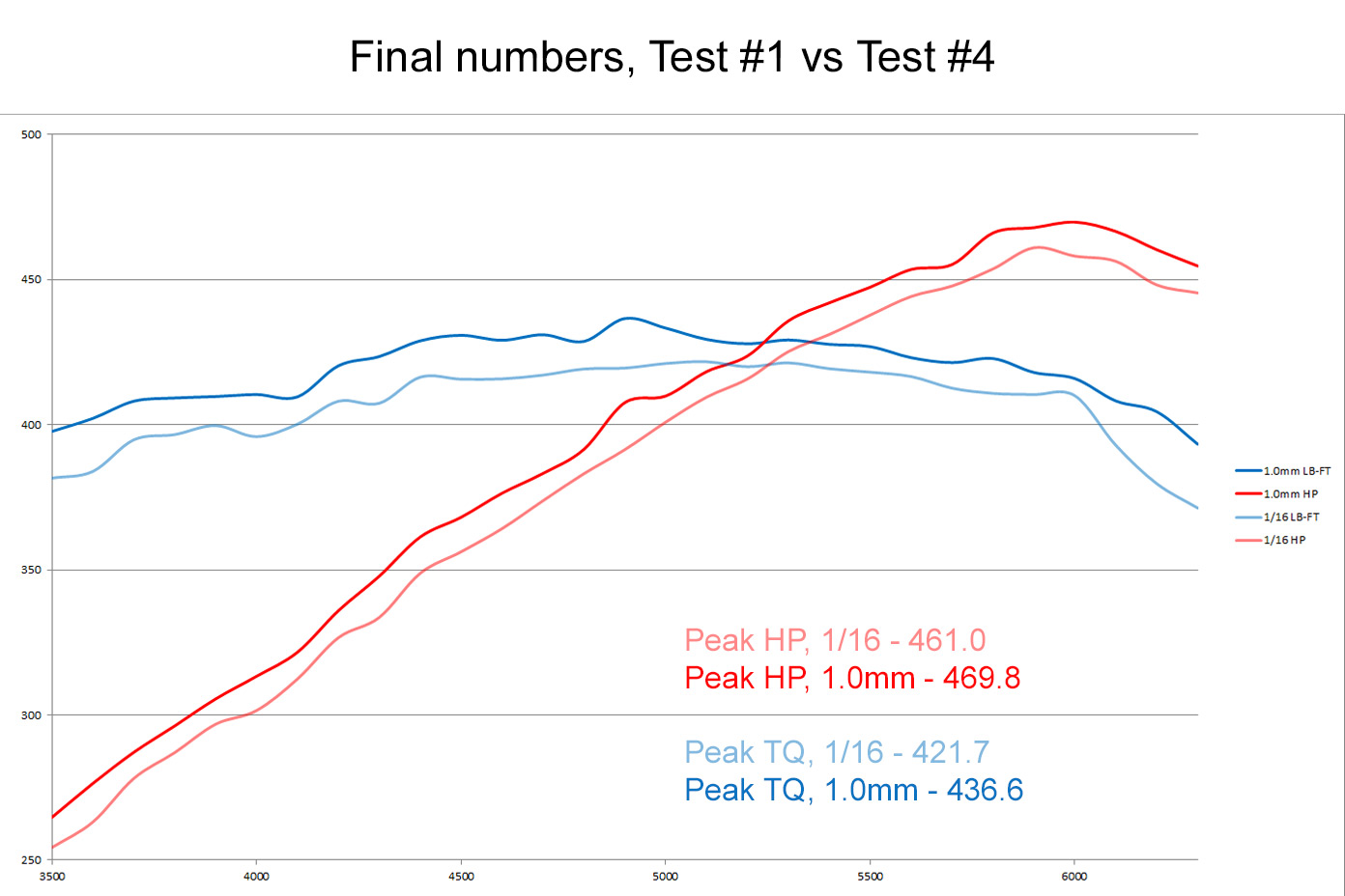
Test Number One – 1/16-inch, 1/16-inch, 3/16-inch
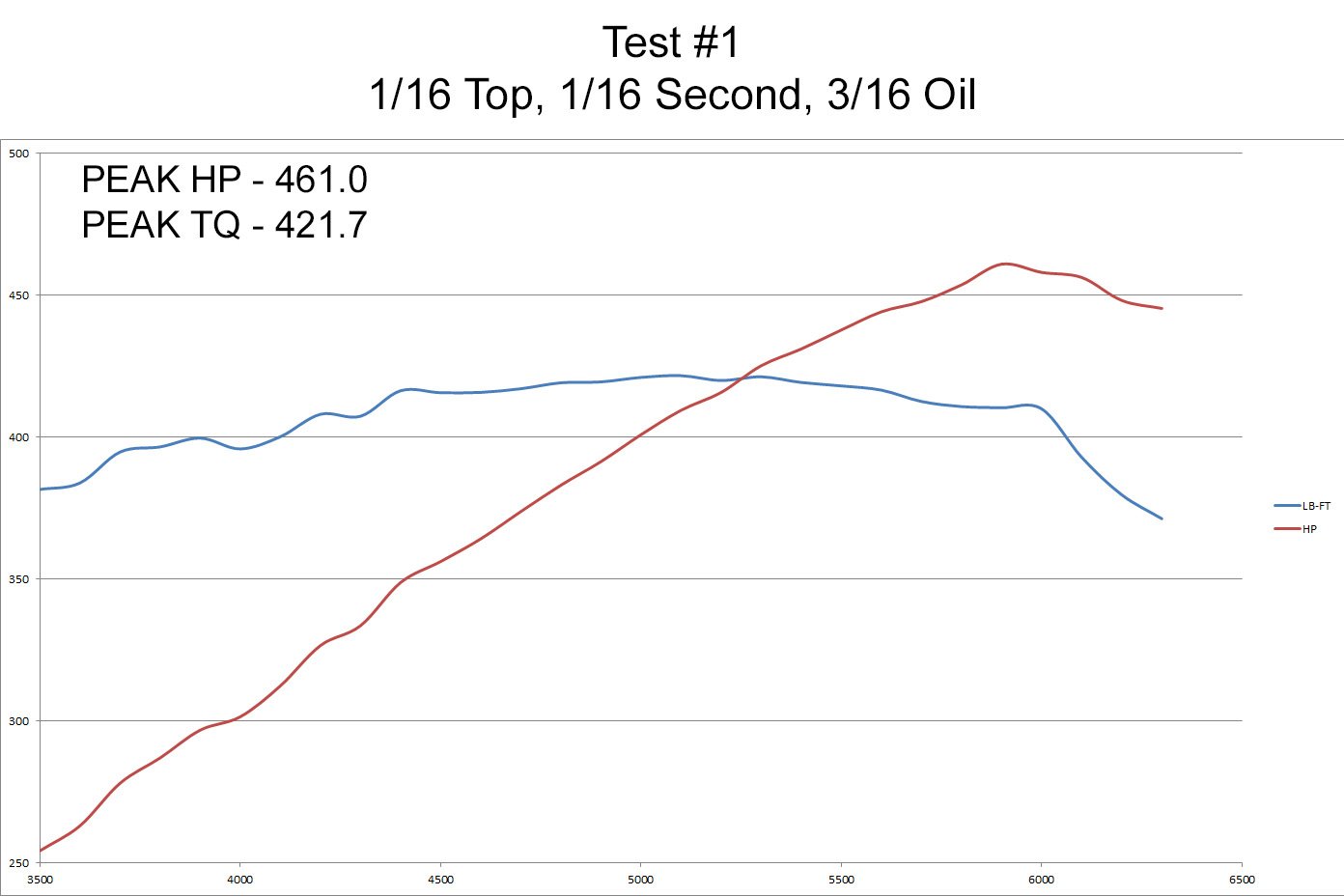

Test number one served as the baseline, with the traditional 1/16-inch top and second rings, with a 3/16-inch oil ring. As you can see, the engine made 461 horsepower and 421 lb-ft of torque, with a peak of 3.27 cfm of blow by at 6300 rpm.
After the test was completed, the engine was torn down and we measured the cylinder bore finish with a profilometer. Here are the results:
RPK = 5.8
RVK = 60
RK = 31.0
Notice how the cylinder bores have changed after the initial break-in of the engine. There is a major change between now and when we first started with a freshly machined block. Now for test number two, the engine was put back together with the 1.5mm, 1.5mm and 3mm piston ring package with a light coat of oil.
Test Number Two – 1.5mm, 1.5mm, 3.0mm
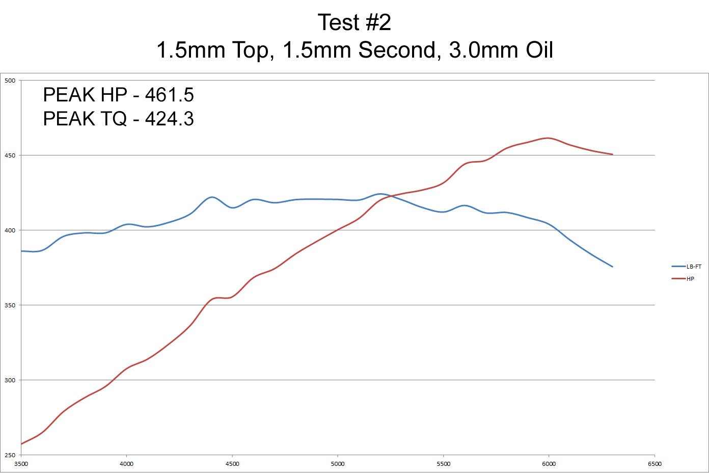
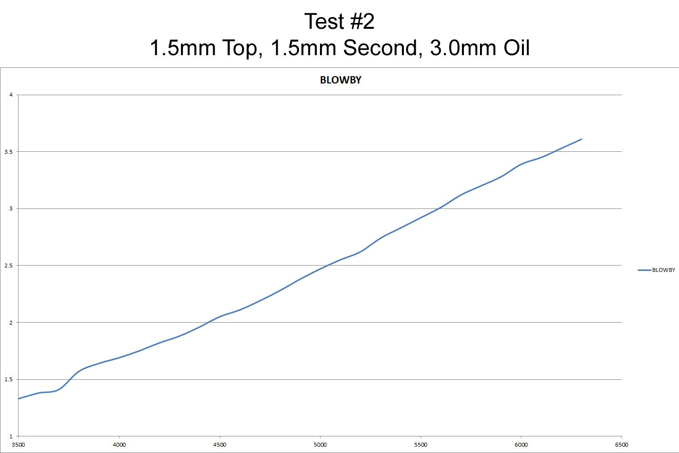
With the slightly thinner 1.5, 1.5, 3.0mm ring package, there were only slight changes to the peak numbers of 461.5 horsepower and 424.3 lb-ft, along with peak blow-by measured at 3.61 cfm.
If you compare the averages of both tests you can see that the engine made just a little more blow-by but picked up almost 4 lb-ft of torque. The engine was then again torn down and the cylinder walls measured again with a profilometer. The results of the cylinder bore finish are very interesting because the new set of piston rings had little effect on the cylinder hone finish.
Cylinder hone results:
RPK = 4.2
RVK = 59
RK = 27.9
The procedure was the same as before, the pistons and rings were changed and reinstalled with a light coat of oil. The engine was reassembled and prepared for the next test this time using .043-inch, .043-inch, and 3mm piston-ring widths.
Test Number Three – .043-inch, .043-inch, 3.0mm
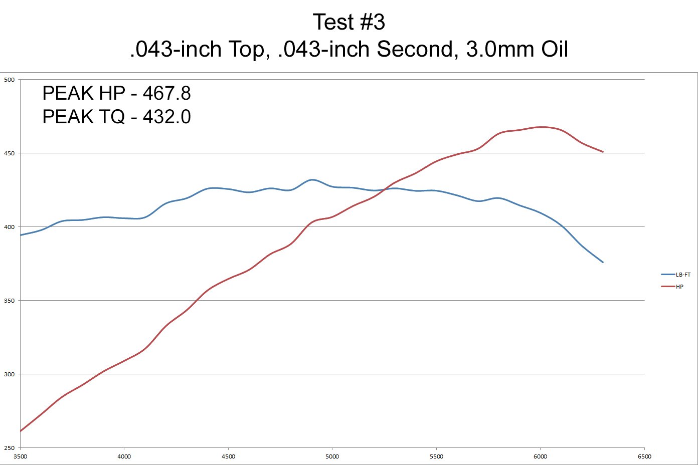
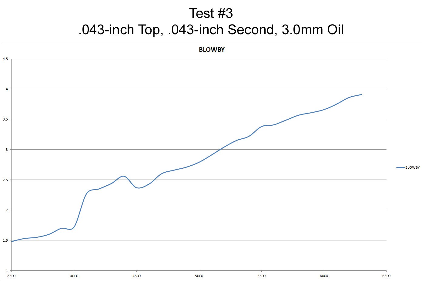
Test 3 is where the real power gains start to be seen with 467.8 horsepower and 432.0 lb-ft, with only a slight increase in blow-by, peaking at 3.91 cfm.
If you compare the averages of this test to the previous one you can really start to see the advantage of the smaller piston ring package. In this test we gained an average of 7 horsepower and 8 lb-ft of torque with just a slight increase in blow-by. The engine was again torn down and the cylinder bores were measured. Here are the results:
RPK = 4.0
RVK = 56
RK = 21.8
If you compare to the last cylinder bore readings there is still little change in the bore finish. The engine was reassembled and prepared for the last test using 1mm, 1mm, and 2.0mm piston rings widths installed with a light coat of oil on the cylinder walls and piston rings.
Test Number Four – 1.0mm, 1.0mm, 2.0mm
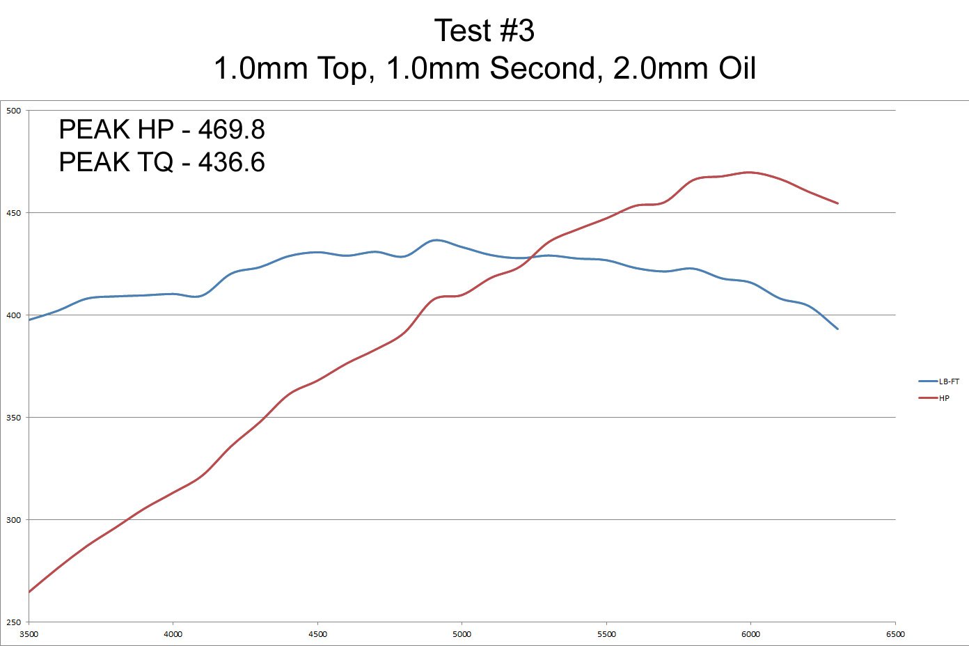
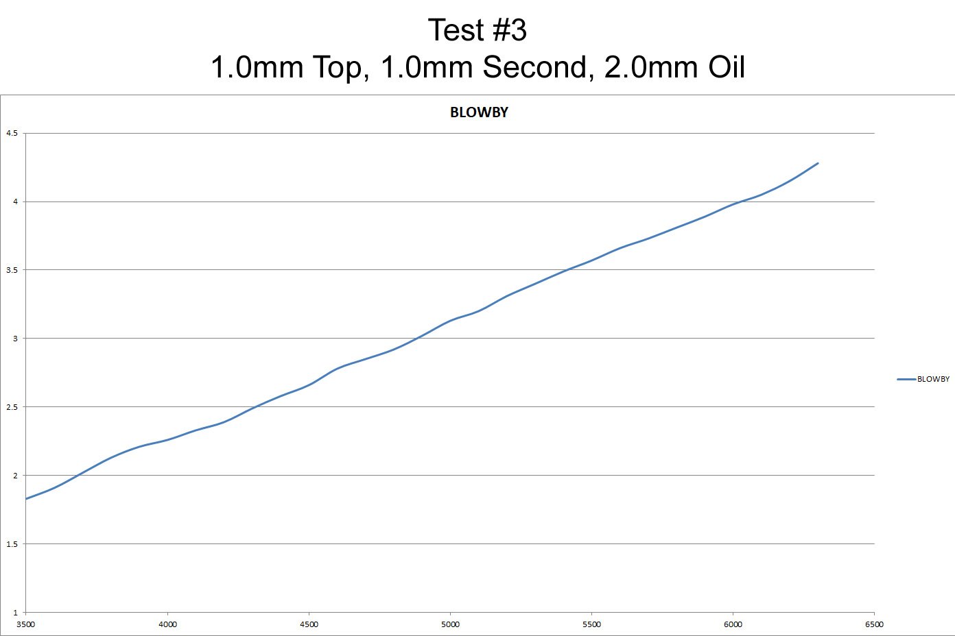
The fourth test showed an additional 2 horsepower gain along with a 4 lb-ft gain in torque for only .004-inch difference in thickness over .043 rings. As expected, there was a 0.37cfm boost in blow-by,
This is a substantial gain from where we first started from. The differences between the four tests prove that there was an average increase of 12 lb-ft of torque and 8 horsepower with only .8 cfm gain in blow-by. Personally, I will take a little more blow-by for that increase in power any day of the week. The engine was again torn down and a final set of cylinder bore finish readings were taken from the profilometer:
RPK = 3.3
RVK = 56
RK = 20.9
There was not much change in the cylinder bore finish after the initial break-in period. This proves that once the piston rings are seated during the break-in and the plateau of the bore finish is established, that the cylinder wall — with the right lubrication — will act as a bearing. The cylinder bore finish only changed by a fraction for the rest of the tests once “broken-in.”