Changing the gearing in a rear differential has been popular since the early days of hot rodding cars. Lower gears (numerically higher) give better acceleration, while higher gears (numerically lower) lend to higher top speeds. Mustangs have always responded well to gearing changes and has been a popular upgrade since the mid 1980s when the 8.8 was first introduced. The best gearing available from the factory was the meager 3.27 ratio only found in AOD equipped cars.
For our own Project Rehab Fox body hatchback, an upgrade to the rear diff seemed to be the logical next strip for our goals at the drag strip. We turned to Motive Gear for all the necessary parts to rebuild and upgrade everything in the rear end of our car.
Parts List
- F88873 Motive 8.8 3.73 Ring and Pinion gear set
- MG22185 Ten Factory 31-spline C-clip axles
- 81-8831-1 Richmond 31-spline spool
- R8.8RMK Motive Master bearing and shim kit
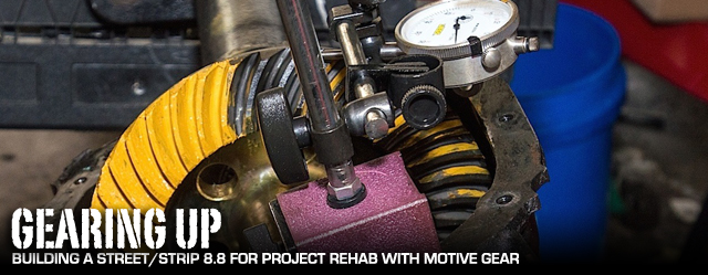
Gearing Up
We use the latest Gleason gear cutting machines to take advantage of ongoing technological improvements in gear design for the right balance of strength and NVH. -Ron Stobaugh, Motive Gear
We’re upgrading not only our rear gears but also the differential and axles as well. Our new gears are Motive’s 3.73s, part number F888373, and according to Motive Gear’s Ron Stobaugh, all of Motive’s gear sets are manufactured in Italy. “We use the latest Gleason gear cutting machines to take advantage of ongoing technological improvements in gear design for the right balance of strength and NVH.” According to Stobaugh this use of the latest in gear cutting technology means Motive’s gear sets will set up consistently and when set up properly, will also eliminate excessive gear noise. The result is a gear set that is tough enough to take to the drag strip, but quiet enough to not drive you mad on the trip there.
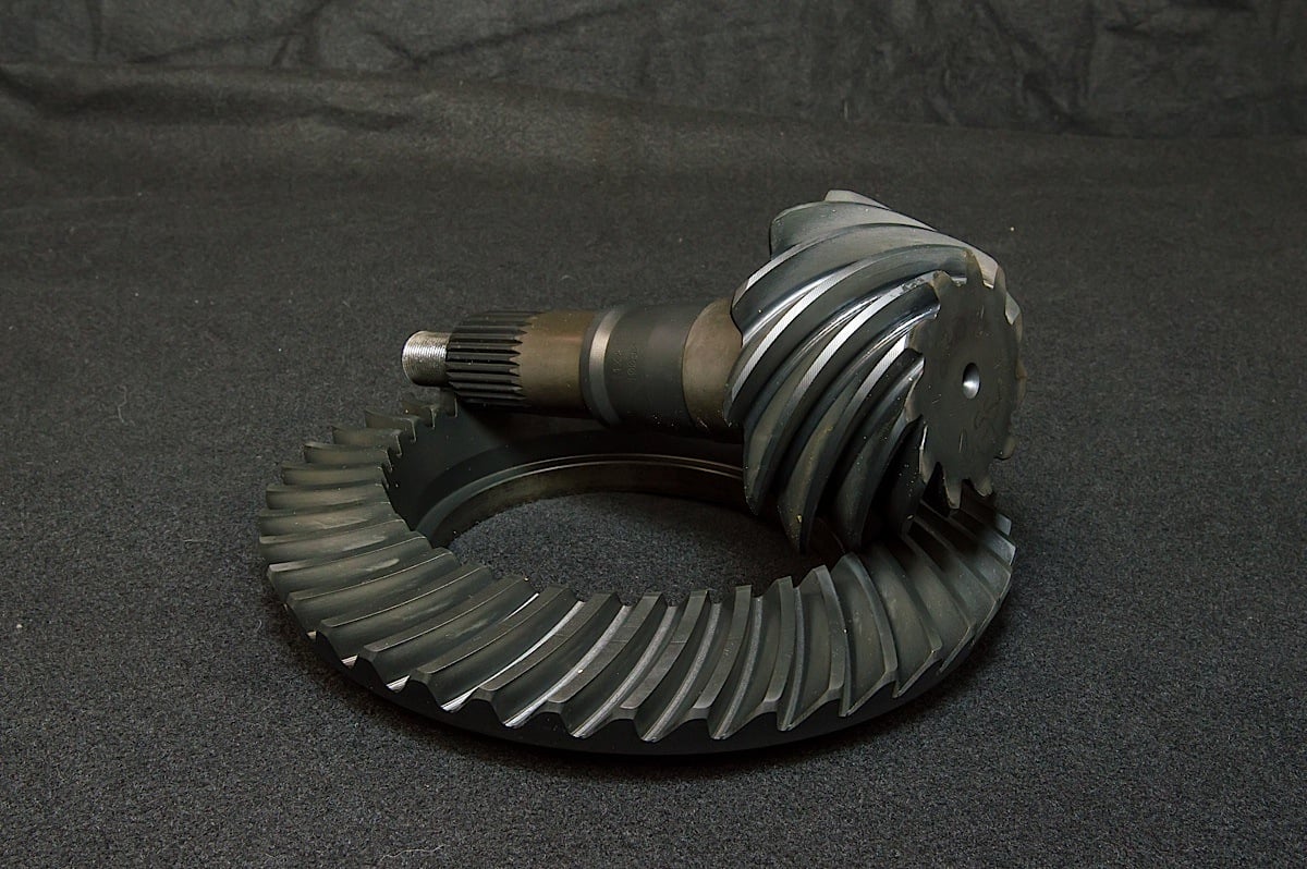
Motive’s axle division is known as Ten Factory and our axles are part number MG22185. These 31-spline units are made from 1541H steel – a medium carbon alloy that also gets Boron added to it for a slightly harder surface, making it better suited for C-clip applications. Stobaugh says, “This is important for C-clip style axles, as the axle shaft acts as the race for the axle bearing.”
According to Stobaugh the 1541H alloy is also well suited for street/strip applications like our Project Rehab, “Street/strip applications need this balance, as ultra-high strength axles made for straight line drag racing only may be too brittle at the axle flange for daily cornering side loads.” The 1541H alloy will give us the strength we need at the drag strip, but won’t become stressed from us driving the car to cruise nights, or back and forth to the track.
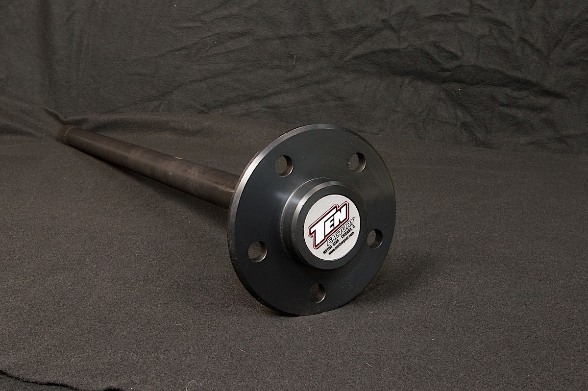
Spooled Rear
Project Rehab is leaning more towards strip duty and away from cornering. With that in mind, we’re going to go for maximum power transfer to the rear wheels at the dragstrip. Motive’s Richmond Gear division sent us one of their 4130 chromoly spools, part number 81-8831-1. The spools are heat treated to ensure strength of the ring gear flange and minimize deflection, while using finite analysis in their design process to strike the right balance between weight and strength.
Bearing The Load
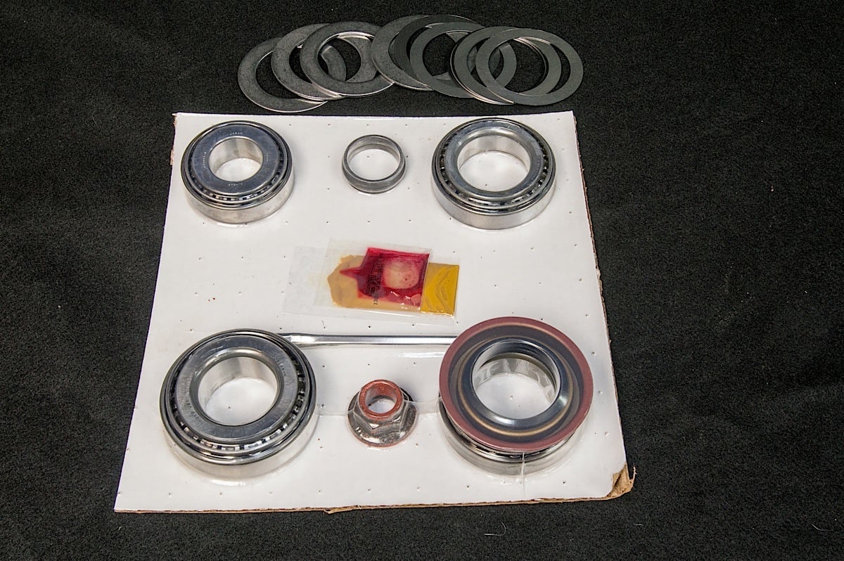
Whenever changes to the gears and the differential are made, new bearings, and shims (or different shims) are needed to get everything set up within specification. For this we ordered one of Motive’s Master Install Kits, part number R8.8RMK. These include either Timken or Koyo bearings for the pinion, and the differential, along with a new pinion seal, pinion nut, crush sleeve, ring gear bolts, gear marking compound, thread locker, and a set of shims for the pinion and differential. According to Stobaugh these are OE quality components that work well in high performance application such as ours.
Chances are that many of our readers have wondered how difficult it is to work on a rear differential or upgrade their gears. This is a job that requires patience, precision, and strict attention to detail. Getting one step wrong may cause you to end up replacing all these parts again, and probably paying a professional to do it for you the second time. It also involves the use of tools that not every DIY’er and bolt-on enthusiast is going to have in their toolbox. The tool investment alone could cost well over $500 if you don’t already have these necessary tools in the garage.
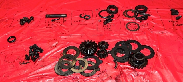
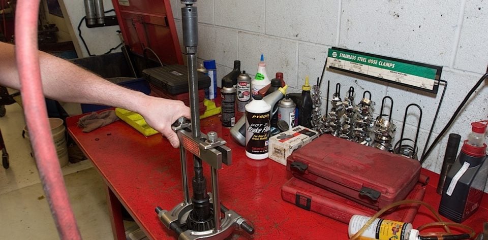
Stay Organized
A method Editor Creason has found to helpful in keeping parts organized on this type of job is to use a plastic table cloth and permanent marker. The 99-cents table cloth is spread over a workbench or table. As each part, or bolt is removed its placed on the table, and then circled and labeled. This keeps parts organized precisely, and makes them easy to find later.
Special Tools Needed:
- Pinon flange holding tool.
- Hydraulic press (optional).
- Large bearing separator set.
- Large drift.
- Large punch.
- Large hammers -deadblow and 3-5 lbs hammer.
- Click-type torque wrench ft-lbs.
- Dial or Scale Torque Wrench Measuring Low scale Inch-lbs.
- Dial gauge with magnetic base capable of reading into the thousandths of an inch.
- Digital caliper capable of reading thousandths of an inch.
- Large and small pry-bars.
- Large Break-away bar 1/2 inch 2 required.
- Impact gun.
- Slide hammer.
- Bearing puller set.
- Bearing and seal driver set.
- 2 or 3-jaw puller.
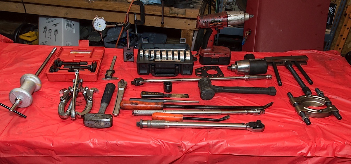
The tools we used for this install, not pictured are the hydraulic press and the inch-pound torque wrench.
There are multiple methods that could be used in place of those we demonstrate in this story. If you have an advanced level of confidence, above normal bolt-on type installs, as well as the right tools, you can complete this operation yourself. If there is any doubt at all in your mind about doing this job however, then pay a professional to do it right the first time.
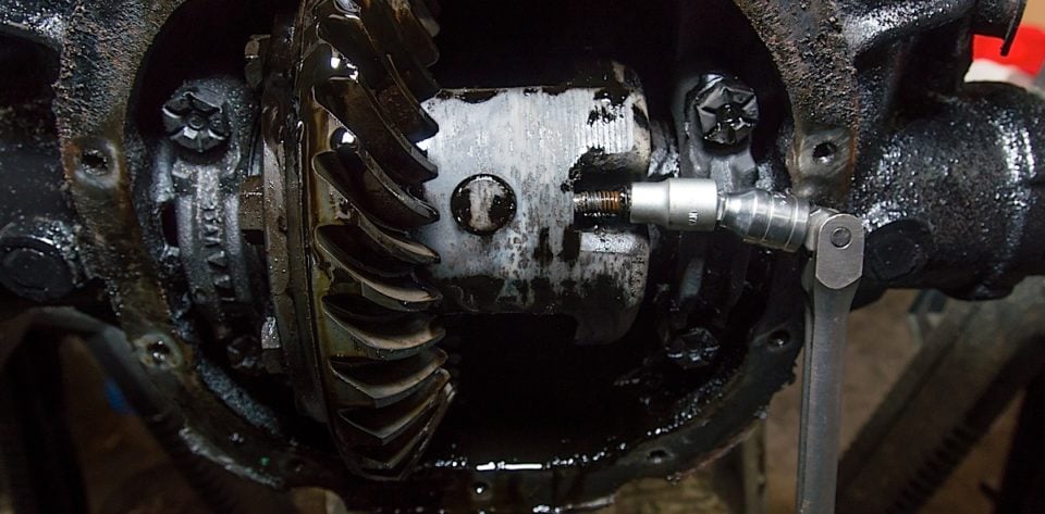
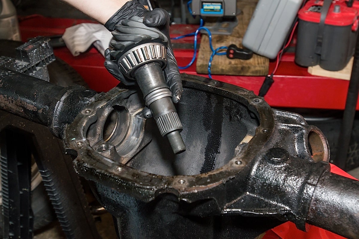
Top Left: With the fluid drained and brakes removed it's time to gain access to our axles. Top Right: We removed the cross-pin bolt. Bottom Left: With the bolt removed we then pulled out the cross-pin. Bottom Right: With the axles and differential removed from the housing, we turned our attention to removing the pinion gear. A 3-jaw puller is used to pull the pinion flange off the gear.
Tearing It Down
With the car lifted off the ground, the driveshaft must be removed first; this will require removing the four 12-point, 12mm bolts that hold it to the pinion flange. Be sure to mark the driveshaft and the pinion flange so they can be matched and easily reconnected in the same position they were removed. The rear sway bar should also be removed to gain better access to the differential cover. There are are just four bolts here.
Drain and Prep
The rear differential needs to be drained next, we have found that removing all but the last top bolt will make draining less messy. While the differential is draining, now is the time to remove the rear brakes. Drum brake cars simply require taking off the rear drums. Disc brake cars will require removing the caliper, caliper bracket, rotor, and possibly the ABS sensor.
Axles
To remove the axles first rotate the differential slowly and locate the differential cross-pin and cross-pin bolt. Carefully remove this bolt, if it’s been removed and reused in the past it may be slightly rounded. A bolt extractor socket comes in handy here.
With the cross-pin bolt out of the way, rotate the differential and remove the cross pin. It should slide out fairly easy with minimal finger pressure. It can also be grabbed by a magnet.
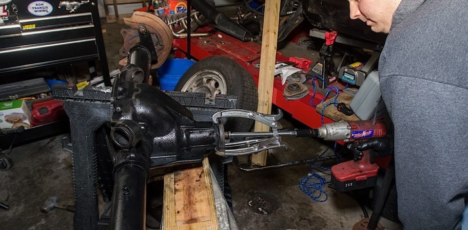
We removed the old pinion bearing using a puller set. This was necessary so we could get the original pinion shim.
Rotate the differential again so that the window is visible – the spring and side gears should be easily viewed. With firm pressure go to each axle flange and press each axle into the housing with a firm shove. The C-clips on the inside end of the axle will now be visible. On some cars these will fall off with a magnet or by slipping off with a finger. Often pliers are needed to remove the C-clips.
With the C-clips out, both axle shafts can now be slid out of the housing. Inspect the bearing area toward the flange end of the axles for scoring. The 8.8 is known for wearing out axle bearings. If the axles are scored it’s time to replace them and the bearings, if you’re doing this job you should at least replace the bearings and seals regardless of axle condition.
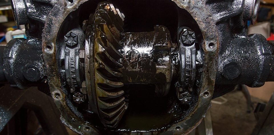
Differential Removal
Remove the two bolts on each differential cap. Notice that the caps have arrows showing which side is out. These caps need to be set aside and marked for their respective sides of the car. With the caps removed, rock the differential back and forth by hand to start disengaging the ring and pinion gears. Use a large pry bar and remove the entire differential assembly. Depending on the age of vehicle, bearing condition, etc, it may take anywhere from minor to heavy force to do this.
As the differential is coming out, be sure to grab the bearing races, and the side shims. These shims need to be marked for the specific side they came from as they will be reused or referenced later.
Pinion Gear
With a pinion flange holding tool installed, hold the pinion in place and use a 27mm socket to remove the pinion nut. An impact gun will make life much easier here. With the pinion nut removed, use a 2 or 3-jaw puller to remove the pinion flange from the pinion gear. The pinion gear may need to be carefully driven out. A large punch and a hammer, or an air hammer works best. Drive in the center of the gear, stay away from the edges as this will mushroom the end of the gear.
With the pinion gear removed go to the inside of the differential and use a large punch or drift to drive out the front pinion gear bearing, race, and pinion seal. Now move to the front of the differential and drive out the inner pinion gear race.
If reusing the stock differential be sure to remove the old ring gear, and bearings, and clean everything thoroughly.
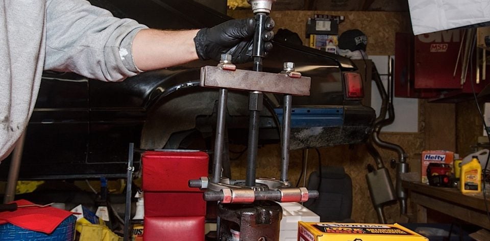
Get The Shim
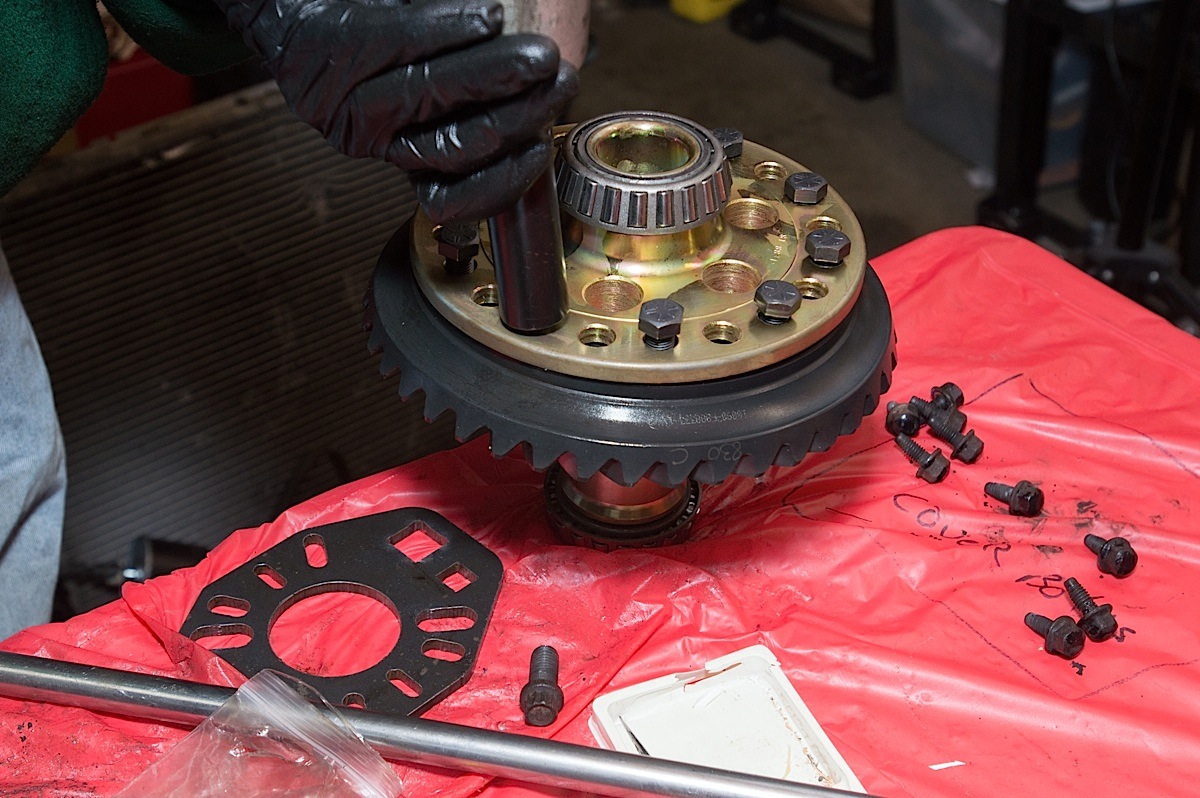
The old pinion gear has two pieces that will be critical to installing our new gears. The first is the pinion gear shim, located behind the pinion bearing. The other is the crush sleeve. We removed the crush sleeve and set it aside for future reference. We then used a large bearing separator and a 10-ton puller to remove the old pinion bearing. This allows us to get our hands on the pinion gear shim. The pinion bearing can also be removed by pressing it off with a hydraulic press, we simply prefer the puller method because it requires only the puller and hand tools to remove the bearing.
If the stock differential is being reused now is also the time to remove it’s bearings. This can be done using a puller and bearing separator, or the roller cages for the bearings can be cut off with a cut-off wheel, and then the rest of the bearing pulled with a jaw-puller.
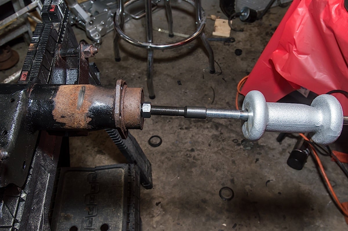
Axle bearings and seals are removed from the housing using a slide hammer and a bearing puller. These can be rented from several different parts stores, or bought online and at several tool stores.
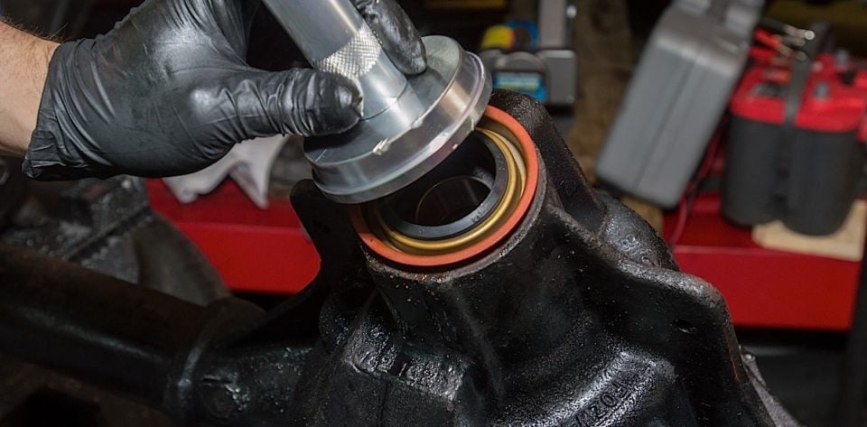
Left: Driving in the inner pinion race. Center left: Driving in the outer pinion bearing race. Center right: The outer pinion bearing is oiled before installing. Right: Driving in the pinion seal.
Assembly
With everything apart the first step in reassembly is to thoroughly clean inside the housing. This really can’t be overdone, two to three bottles of brake clean and some shop rags should do the trick. The goal here is to remove any old dirt, debris, and oil from the housing so the new bearings and races have a clean place to ride, free of contamination.
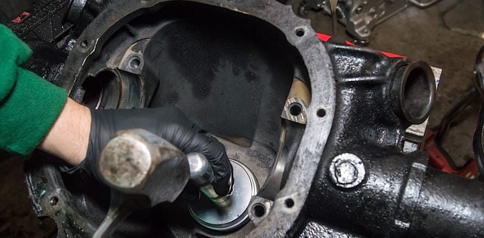
Pinion
Using a bearing and seal installer/driver, carefully drive in the new races for the inner and outer pinion bearings. We recommend smearing a few drops of gear lube on the outside of these races to help drive them in properly. How far to drive these is a matter of listening and feeling. The actual sound of the hammer contacting the driving tool will change pitch and tone once the seal is driven home, the hammer blow will also have a different feel when it hits the handle of the driving tool.
The inner pinion bearing must be pressed or driven onto the pinion gear. First the shim is dropped on so that it goes all the way to the gear end of the pinion shaft. We recommend using a synthetic gear oil to lubricate the inside of the new pinion bearing, this will ease installation. Using a long punch and hammer, the pinion bearing can be carefully driven onto the pinion. The trick here is to work around the bearing and drive on the inner race area where it is flat. Just like the races that were driven into the differential housing, the feel, and sound heard will change when the bearing is all the way into position.
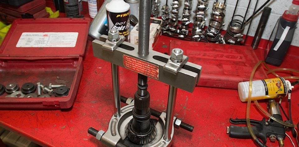
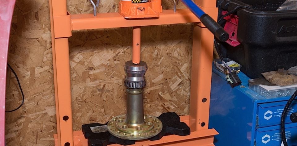
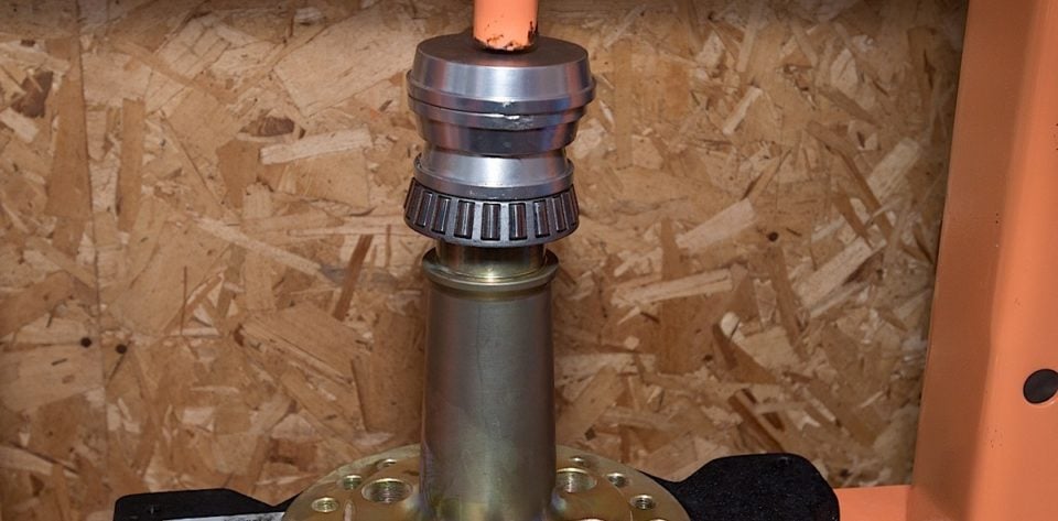
We used a hydraulic press to install the bearings onto our Richmond spool.
Installing this bearing can also be done with a hydraulic press. Also if driving on with a long punch, if the inner area of the bearing is nicked, this does not ruin the bearing. The load on this bearing is on the outside of the rollers, closest to the pinion gear.
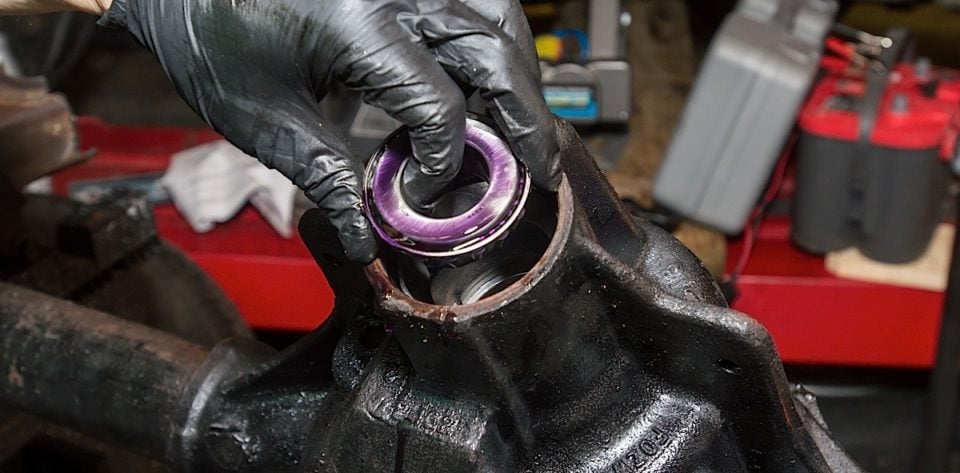
The outer pinion bearing can be placed in through the front of the housing next. Oil all the rollers on this bearing prior to installing it. This is followed by the pinion seal. A few drops of gear oil on the lip of the seal will also make the pinion seal go in easier. It’s driven in with a bearing and seal drive as well.
Setting Preload
Preload is perhaps the most difficult portion of setting up the rear differential and there are two methods for doing this next part. Regardless setting preload requires patience and is often a trial and error process, especially for first-timers. Pinion bearing preload is critical to proper pinion bearing wear and pinion gear life.
Method 1
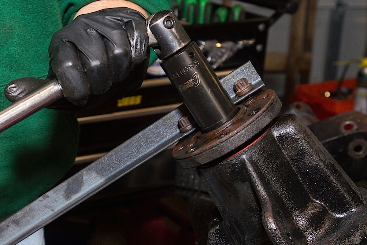
Lubricate the pinion bearing and then slide on a new crush sleeve. Place the pinion gear into the differential housing, seating it into the inner pinion bearing race. Now attach the pinion flange on the other side, and start the pinion nut.
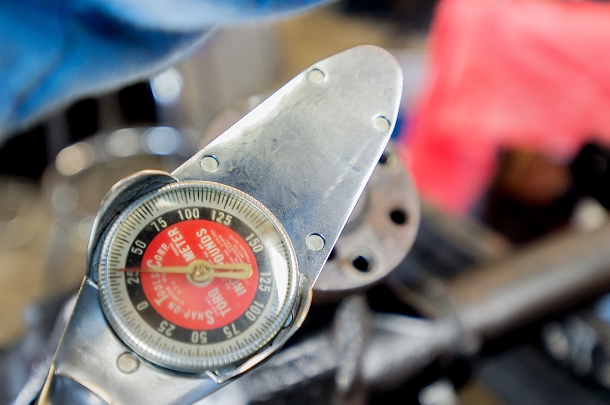
Use an impact gun and tighten the pinion nut down, this will typically stall most 1/2-inch impact guns. Now check the rotational force required to spin the pinion by placing an inch-pound torque wrench on the pinion nut and rotating it. The goal is to achieve 16-28 inch-pounds of rotational force.
If this rotational force is lower than spec, the goal is to tighten the pinion nut further. This crushes the crush sleeve more, drawing the pinion bearing further into the race, increasing its preload. Bear in mind that a difference of 0.001-inch in the crush sleeve can have an affect on the preload. Using a pinion flange holding tool and breaker bar, carefully tighten the pinion nut further. We don’t recommend going more than 1/8-1/4 of a turn on the pinion nut without checking preload. Once the crush sleeve is over-crushed, there is no going back. If the rotational torque is too high when checked, the pinion gear must be removed from the housing, a new crush sleeve installed, and the process started over.
Method 2
This method replaces the crush sleeve with a solid spacer and shims to achieve pre-load. The spacer and shims are reusable, so if preload needs to be increased it can easily be done by changing shims.
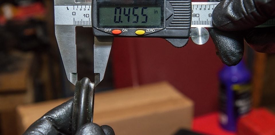
Left; We measure the used crush sleeve, and record its height. Right: We measure the solid pinion spacer and will add shims to achieve the same height as the used crush sleeve as a starting point.
Start by measuring the crush sleeve that came off the old pinion gear, and record that measurement. Measure the solid spacer, and then add shims to it so that the total installed height will be the same as the old crush sleeve.
Now with the inner pinion bearing lubricated, and the spacer and shims on the pinion gear shaft, install the pinion bearing, and pinion gear flange. Tighten the pinion nut to 125 ft-lbs of torque. Check the rotational torque with dial or bar-type inch-pound torque wrench, the spec is the same as with a crush sleeve.
If preload is too low disassemble and remove the smallest shim. If preload is too great, disassemble and add a small shim. This is a trial and error process, but can be far less frustrating than going through 3-4 crush sleeves to get the correct bearing preload.
More Assembly
We installed new bearings onto our Richmond spool using a hydraulic press. These can be driven on by hand the same way the pinion bearing was driven on, or pressed to save time. If the stock carrier is to be reused, simply install the new bearings onto it.
Ring Gear
The ring gear is placed onto our spool next. This is a tight fit, and sometimes requires the gear to be pressed on. With the ring gear in place each ring gear bolt is torqued to 100 ft-lbs
With all of the pinion gear bolts started, and thread locker on each bolt, we tighten in a cross-cross pattern with our impact to draw the gear to the flange of the spool. If the gear won’t draw up, a press can be used.
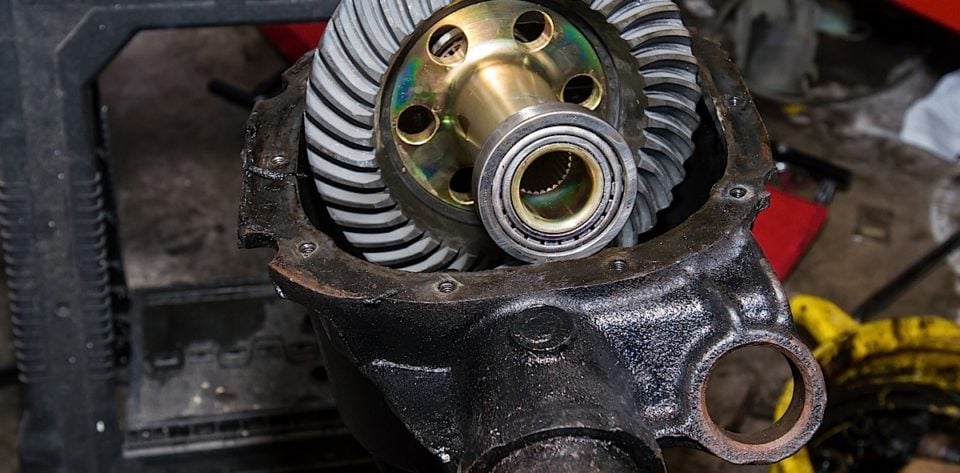
We lubricated the differential bearings, then with our ring gear and new bearings in position the spool is set into the differential housing. Make sure to install the side shims that were previously removed during disassembly. The left side bearing, race, and shims are installed first. Then with the assembly in the housing the right side race and shims can be installed. Now the differential caps can be installed on the correct side each, followed by the new bearing caps. The caps are torqued to 100 ft-lbs.
Backlash
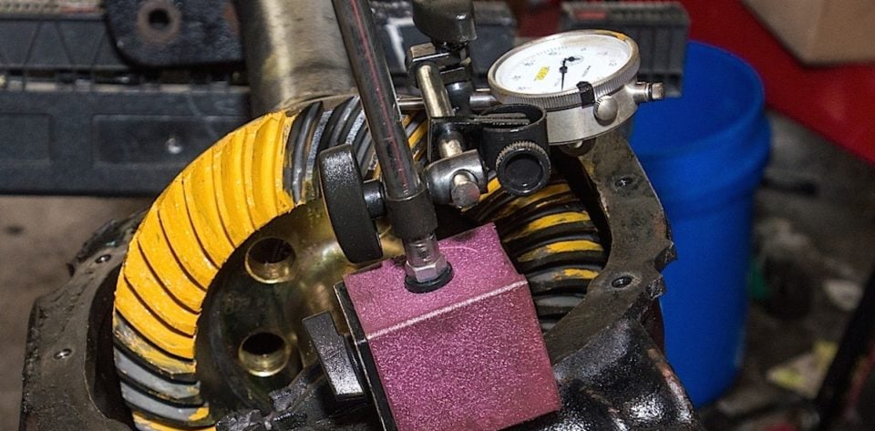
Checking backlash requires using a dial indicator with magnetic base. Rotate the ring gear up (forward) and place the tip of the dial gauge on a gear tooth, then zero the gauge. Now the ring gear is rocked backward carefully until it makes contact with the pinion gear again. The measurement on the gauge is known as backlash, and Ford specifies a backlash of 0.008-0.012-inch. Too much and gear damage occurs, as well as a clunk noise on acceleration. Too tight of backlash will cause excessive heat and damage the gears and bearings. Backlash is adjusted via the side carrier shims.
Left: We installed the spool with the ring gear. Right: With the cap bolts torqued, we checked backlash using a dial gauge with magnetic base.
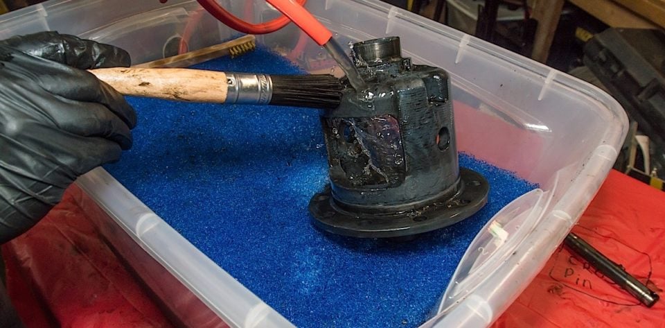
Tooth Pattern
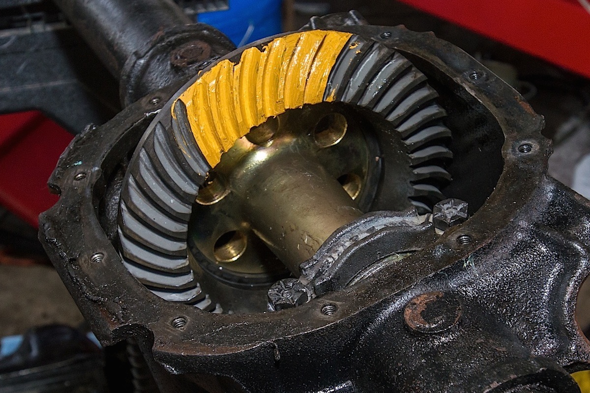
Getting the correct mesh of ring and pinion gear teeth is key to gear life, and low noise. Motive provides a checking compound in their kit, which is a thick yellow colored dye. We painted several teeth then rotated the differential forward and backward to check tooth pattern.
We’re looking for a tooth pattern that marks the ring gear near the center on both apply (top of the ring gear tooth) and coast (bottom of the ring gear tooth). If this is incorrect, the pinion gear depth must be changed by changing the pinion gear shim.
Axles
Finally install the new axle bearings and seals using an axle bearing and seal driver. We slid in the new Ten Factory axles, and if you’re using C-clips now is the time to reinstall them. In our case we are using C-clip eliminators which we’ll discuss in a future article. With the axles in place, use a bead of silicone to create a new seal for the cover. Now install the cover, and fill the differential with proper gear oil, and if using a clutch type differential add the appropriate friction modifier.
With gears, and new, stronger components installed in Project Rehab’s differential, we’re ready to hit the track after doing a little street driving to make sure the parts are broken in properly. We can’t wait for winter to end, and to make our first pass at the track with our upgraded rear axle package from Motive Gear.