

Over the past few years, the S197 Mustang made a significant jump in popularity at the drag strip. While it’s not overly surprising, this surge is largely due to the market being fairly saturated with these affordable Mustangs. Combine this with the absolute juggernaut that is the Coyote engine, and you have a recipe for serious street and track performance.
Whether your S197 is primarily a racer or simply a fun daily driver, understanding the rear suspension geometry can be extremely beneficial. The same principals that make single-digit race cars work also apply to the guy with nothing more than lowering springs who has never been to the track.
BMR Suspension of Seffner, Florida, specializes in suspension components for Mustang enthusiasts. The company builds performance suspension components that are designed to give customers the strength and adjustability to achieve nearly any level of performance without having to use full race-style parts that aren’t designed for street use. We sat down with BMR to discuss some of the design features used to allow enthusiasts to get just about any amount of power to the ground, as the company does with its own in-house project car…
Whether you have a basic street car, or an all-out race car, BMR has the parts to add the adjustability needed to correct any geometry issues.—Brett Rockey, BMR

Many factors are at play when power is applied to the chassis, but for the sake of this discussion, we are going to focus on rear suspension geometry. Most of us are familiar with the term instant center, but for those who aren’t, the instant center is the intersection point of the upper and lower control arms if both links were extended until they intersected. This point can be changed by raising or lowering the mounting points of the upper or lower control arms.
Changing this point in relation to the car’s center of gravity has a big influence on the chassis, and how power is applied to the tires. The higher the point is, the more aggressive power will be applied. The lower the point is, the softer the hit will be. The factory S197 three-link suspension system does not allow for any instant-center adjustability, but BMR Suspension has some popular components that allow for this.
Southern Relocation

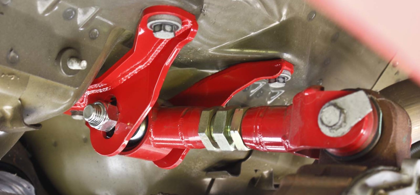
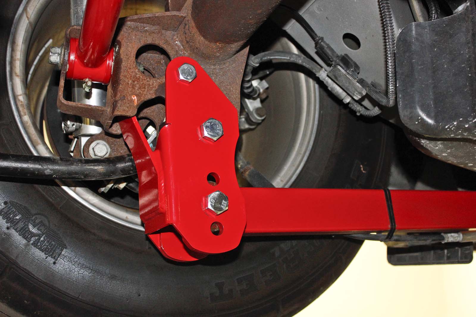
BMR Suspension’s Lower Control Arm Relocation Brackets (PN CAB005) allow you to run the rearend side of the lower control arms in either the factory position or three lower positions. This allows you to correct the lower control arm geometry for lowered Mustangs, or fine-tune the instant-center location and anti-squat percentage for perfect launches.
As you might expect, control arm relocation brackets allow you to change the rear lower control arm mounting location. This is effective for correcting rear suspension geometry on lowered cars when the LCA mount of the body becomes lower than the rearend side. This does a few things. Firstly, it changes the instant center location. Second, it increases the anti-squat percentage.
Anti-squat is the suspension’s mechanical resistance to compression due to forces from the engine. This means when power is applied to the rear suspension, the force of the engine is being applied to the links instead of the body of the car. This causes the rear tires to separate from the body instead of the body squatting over the tires. The benefit to anti-squat with big power Mustangs is that the tires are driven into the ground hard, which can help with traction. The negative side of more anti-squat is that the car will need rear shocks with the ability to control the aggressive axle movement. Without “enough” rear shock, the rear can react so quickly that it will literally bounce the tire off the ground, causing the suspension to unload and spin the tires.

By running the lower control arms in one of the lower holes, the instant-center position moves up and closer to the rear of the car (assuming the upper control arm position remains unchanged). This also adds anti-squat percentage, giving you a more aggressive application of power.
Getting The Upper Hand

BMR Suspension’s Upper Control Arm Mount (PN UCM002) bolts in the stock location and features three mounting positions for the front of the upper control arm. This allows for further tuning of the rear suspension geometry.
Similar to BMR’s lower control arm relocation brackets, its adjustable upper control arm mount features three positions to further increase the level of adjustability in the rear suspension. When combined with the lower control arm brackets you have 12 possible instant center positions. For the average enthusiast, this gives you the ability to correct the rear suspension geometry at almost any level of drop. For the race enthusiast, you have the ability to move the instant center location and run the amount of anti-squat of your choosing to help tune the chassis for hard launches.
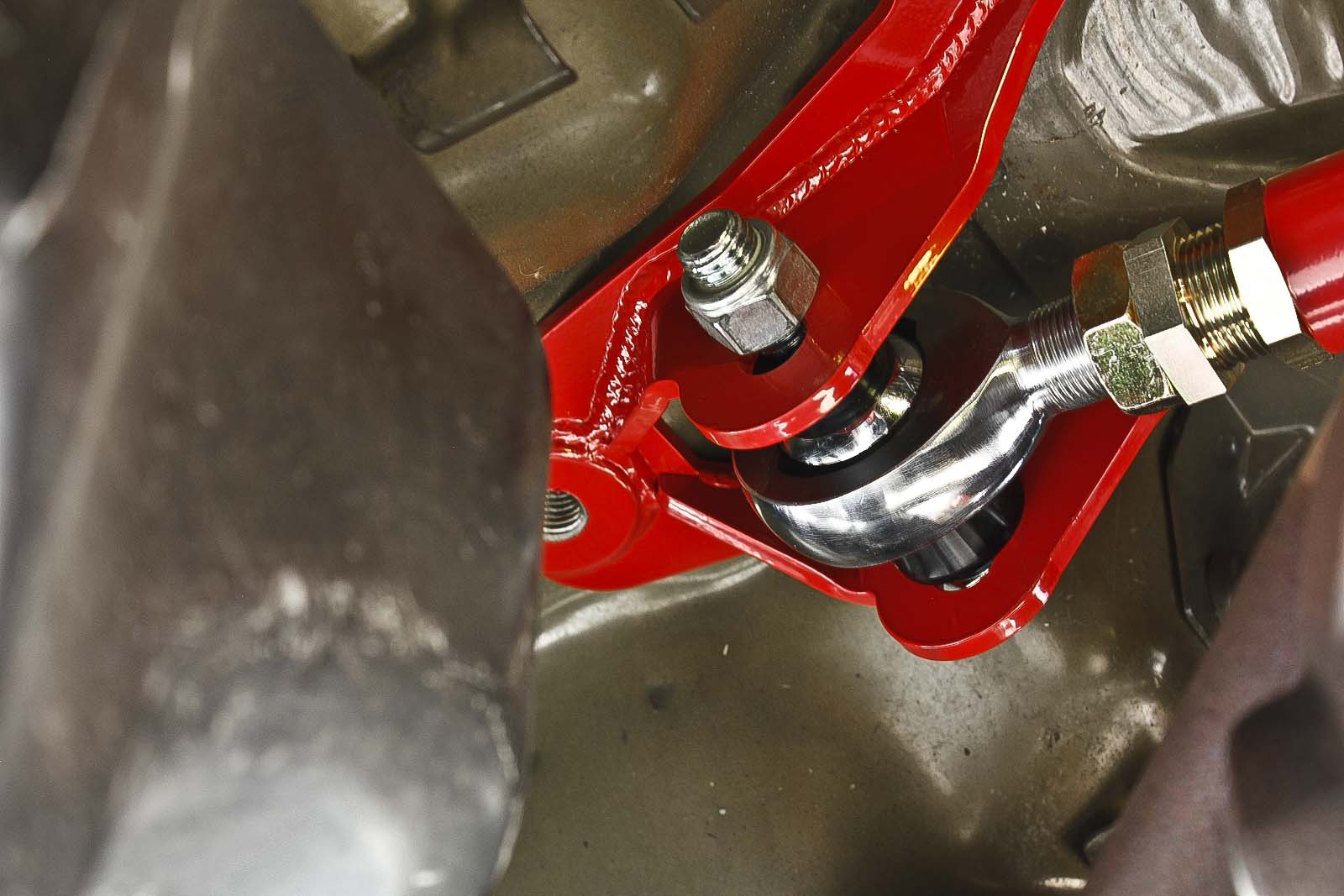
Whether you run a factory upper control arm or a beefy arm like either of these from BMR, the position of the front mount has a big impact on power application.
Anti-squat is measured using the instant center location and the neutral line. The neutral line is a line from the center of the rear tire contact patch to the center of gravity at the front axle centerline. If the instant center falls on this line, you will have 100-percent anti squat (this is considered neutral). As power is applied to the chassis, the body and tires should not separate, and the body should not squat on the tire; all of the power should be applied to moving the car forward. In a perfect world, this is the most efficient scenario. The higher you get above the neutral line, the more the axle will separate from the body. Inversely, the less percentage of anti-squat, the more the body will squat over the rear tires.
Plotting Instant Center

Measuring correctly is critical to achieving accurate results when plotting the rear suspension geometry. The effective length of the upper and lower control arms must be used. This means you need to have the distance from front mount to rear mount on a straight plane. The actual length of the arms will yield inaccurate information. It is also important to correctly measure the center of gravity height for accurate anti-squat percentages. For this we recommend measuring the height at the center of the water pump pulley for NA cars. For most power adder cars we recommend measuring to the top of the water pump pulley. You will also need an accurate wheelbase measurement and tire diameter.
Plotting your instant center can be a lengthy and tedious process. The car needs to be level and at ride height, preferably with the weight on the tires. Instant center location will differ from car to car based on ride height, tire size, air pressure, and suspension-link location. For the sake of this example, we plotted all of the possible IC locations on BMR’s 2011 Mustang GT with stock-style wheels and tires. The car is equipped with BMR’s Lower Control Arm Relocation Brackets (PN CAB005), Lower Control Arms (PN TCA019), Adjustable Upper Control Arm Mount (PN UCM002), and Adjustable Spherical Upper Control Arm (PN UTCA033).
The effective control arms lengths are measured at 18.25 inches for the lowers and 9.4 inches for the upper. You will also need to measure the center of gravity. Normally, center of gravity height is measured based on the camshaft location, but this is not applicable with overhead cam engines. There are a few different ways to measure center of gravity–but for naturally aspirated cars–we normally go by the center of the water pump pulley on Mod-motor and Coyote cars. For most power-adder applications, we normally recommend measuring from the top edge of the water pump pulley.

Having the correct neutral line is critical for accurate anti-squat percentages. This line is measured from the center of the rear tire contact patch to the center of gravity height at the front axle centerline. Once you have this line plotted out, it is easy to figure out the anti-squat percentage based on the instant center location. If the instant center falls on the neutral line, you have 100-percent anti-squat. If the instant center is above the line you have more than 100 percent, less than 100 percent if it falls below the line.
Once you have all of your measurements, you’ll need to plot the suspension. There are plenty of instant-center calculators on the Internet, and we used Baseline Suspension’s General IC Calculator. Simply input your measurements, wheelbase, tire diameter, and height of the center of gravity, and it will give you all the pertinent information.
So long as your measurements are accurate, the results will be accurate.
The calculator will give you the instant-center length and height, as well as the anti-squat percentage. With this information, you will be able to make an informed decision about what changes you need to make to improve your launches. It is important to know that not all instant-center and anti-squat settings will work for every setup. Since big changes (to either setting) directly affect how power is applied to the tire and the chassis, it may take some trial-and-error to figure out what will work best for your combination. Tire pressure, along with adjustable shocks, will also need to be changed to optimize any setup.
Making The Numbers Work

Although this illustration can be a bit confusing, it is just that–an illustration. When you plot out the 12 possible instant center locations, it’s easy to see that you have a few clustered together, a few further out, and few so far out, they aren’t even in the illustration. Depending on your setup, engine combo, power output, tire, etc., some instant center locations will work well, and some not so well. Each position will want different air pressures and shock settings to optimize performance.
BMR Suspension S197 Rear Suspension Measurements (2011 Mustang GT)
Center Of Gravity: 21.5 inches (Center Of Water Pump Pulley)
Wheelbase: 107.25 inches
Tire Diameter: 28 inches
Lower Control Arms
Effective Length: 18.25 inches
Front Mount Height: 6.5 inches
Rear Mount Heights: 4 inches, 5 inches, 6 inches, 8 inches
Upper Control Arm
Effective Length: 9.4 inches
Front Mount Heights: 18.5 inches, 19.25 inches, 20.0 inches
Rear Mount Height: 20.5 inches
It is important to know that if you have the correct parts, you have the ability to tune the chassis’ launch characteristics–so it performs the way you want it to. Finding the right location can be a long and tedious process that involves a lot of testing; but the end result can be extremely rewarding, if you are willing to put in the time and effort.
Every car is different, and the instant center and anti-squat numbers are going to vary per application. But a similar configuration will yield similar results. Below are three examples of popular S197 control arm locations using BMR’s adjustable upper mount and control arm relocation brackets. These illustrations are designed to give you an approximate idea of where the instant center and anti-squat percentages would be in other S197s with similar configurations. For accuracy, we recommend measuring and plotting out your suspension system.
Here’s a look at some common adjustments and how they impact the instant-center and anti-squat characteristics of a 2011-2014 Mustang…
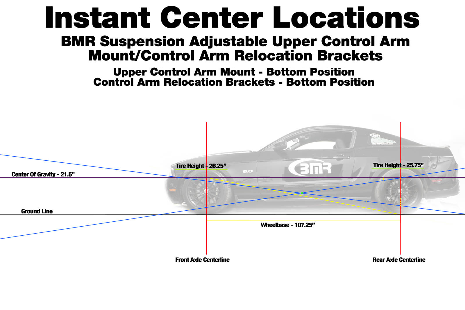
Upper Control Arm Effective Length: 9.4 inches; Lower Control Arm Effective Length: 18.25 inches; Rear Upper Control Arm Bolt Mount Height: 20.5 inches; Front Upper Control Arm Mount Height: 18.5 inches; Rear Lower Control Arm Mount Height: 4 inches; Front Lower Control Arm Mount Height: 6.5 inches; Center Of Gravity: 21.5 inches; Wheelbase: 107 inches; Tire Diameter: 28 inches; Anti-Squat Percentage: 124.44 percent; Instant-Center Length: 47.18 inches; Instant-Center Height: 10.46 inches
Running the control arms in the bottom position of both the upper control arm mount and relocation brackets will give you the most aggressive setup available. By running the instant center in the shortest possible position with a large amount of anti-squat, the rear tires will be driven into the ground aggressively as power is applied. BMR recommends this type of setting for people who primarily race their Mustang, and have large amounts of power, requiring the maximum amount of traction possible.
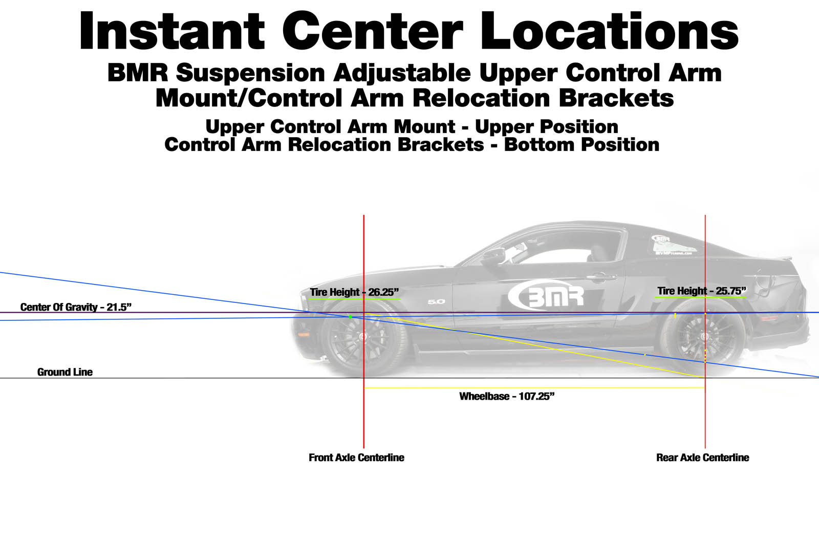
Upper Control Arm Effective Length: 9.4 inches; Lower Control Arm Effective Length: 18.25 inches; Rear Upper Control Arm Bolt Mount Height: 20.5 inches; Front Upper Control Arm Mount Height: 20.0 inches; Rear Lower Control Arm Mount Height: 4 inches; Front Lower Control Arm Mount Height: 6.5 inches; Center Of Gravity: 21.5 inches; Wheelbase: 107 inches; Tire Diameter: 28 inches; Anti-Squat Percentage: 95.50 percent; Instant-Center Length: 120.45 inches; Instant-Center Height: 20.50 inches
Running the upper control arm in the upper position and the lower control arms in the bottom positions will give you a great setup for a street performance application. The instant center is in a position that isn’t overly aggressive, and the anti-squat percentage is just under 100 percent. this means the body will not squat much and the axle will not drop away from the body much. Power will be applied to driving the car forward. This setup is great for people with moderate amounts of horsepower who primarily use their Mustang on the street.
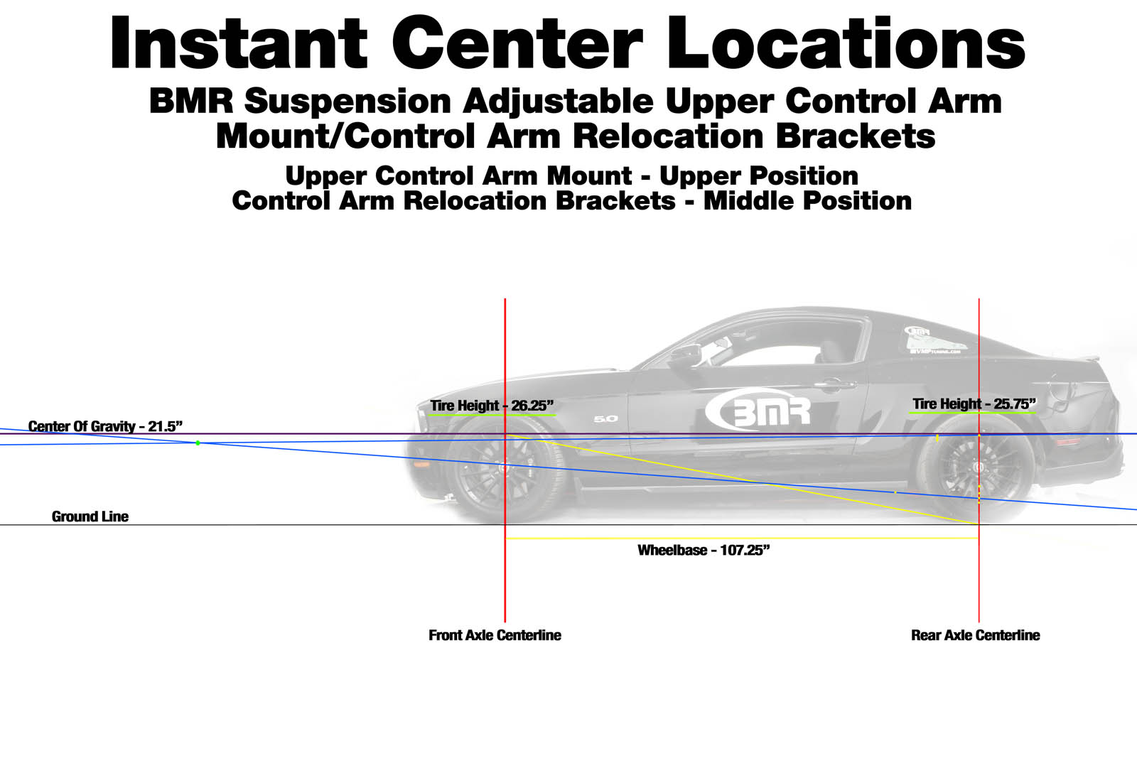
Upper Control Arm Effective Length: 9.4 inches; Lower Control Arm Effective Length: 18.25 inches; Rear Upper Control Arm Bolt Mount Height: 20.5 inches; Front Upper Control Arm Mount Height: 20 inches; Rear Lower Control Arm Mount Height: 5 inches; Front Lower Control Arm Mount Height: 6.5 inches; Center Of Gravity: 21.5 inches; Wheelbase: 107 inches; Tire Diameter: 28 inches; Anti Squat Percentage: 61.00; Instant Center Length: 188.58 inches; Instant Center Height: 20.50 inches
Running the upper control arm in the upper position and the lower control arms in the middle positions, you extend the instant center well beyond the nose of the car, while keeping the position relatively low in relation to the neutral line. This decreases the anti-squat percentage, which will allow the body to squat over the rear tires. This configuration will not be very aggressive and is great for a basic daily driver. BMR recommends setups similar to this for stock power and stock height vehicle that will only see daily street use.
Where The Rubber Meets The Road
When it comes to setting up the rear suspension of your S197, you can set it up to give you options. Some will work really well, others won’t. Finding the right instant-center position and anti-squat percentage can take some trial-and-error; but putting in the time and effort can be rewarding. It will also make a huge difference in the performance of the car.
[Ed note: This story was written by contributor Pete Epple, an employee of BMR Suspension. While the article does feature BMR products, we felt that the value of the information outweighed any negatives from this relationship. Thus, it is universally applicable, no matter what suspension you choose.]